Previous: Sub-systems
Autonomous Robot
MCU programming
Programming the MCU on-chip peripherals went pretty well. There was a fair amount common code between the MCUs (startup, RTC, serial I/O, etc). Two things did take more time than I expected:
- the velocity motion control algorithm development and its debugging (started in assembly, then redone in C)
- and the serial data parsing and handling
Because the MCUs are daisy-chained, they have to pass data not meant for them and respond to data that is addressed to them. This requires bullet-proof code that does not fail under constant data flow - while the MCU additionally performs its sensor/motion interfacing tasks.
Each MCU has a simple command and reporting protocol. It looks at each incoming ASCII word (separated by whitespace). Commands are in lower case. The first character is the MCU address. The second character is the function command. Command arguments follow when needed. Recognized commands are echoed verbatim (because multiple MCUs might need to respond). The MCU also gives an upper case response/report.
Main controller
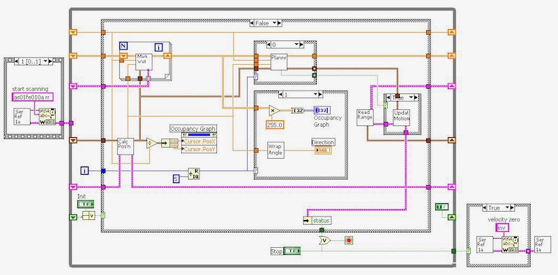
In my day job, I write software in a language called LabVIEW (from National Instruments, Austin, TX). It is a graphical language that is very effective for test and measurement applications. Writing code in LabVIEW is much like drawing an electronic circuit diagram. In fact, I think that people with a hardware background feel more immediately comfortable with it.
This is the main code for the robot system controller (a LabVIEW diagram).
LabVIEW's graphical nature also works well with graphical output for display of mapped areas.
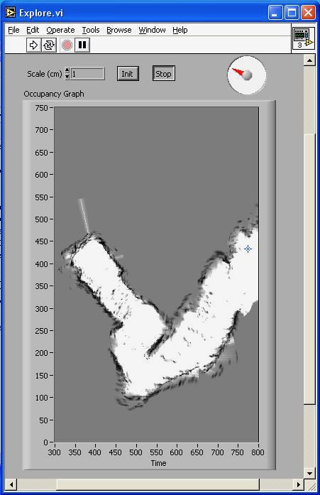
I started development with a proof-of-concept map of a short hallway in our house. This is a simple occupancy grid and each dot is an indication of a surface as detected by an optical ranger. There was no statistical processing. Each dot is a square centimeter and the robot only moved in a straight line at this time.
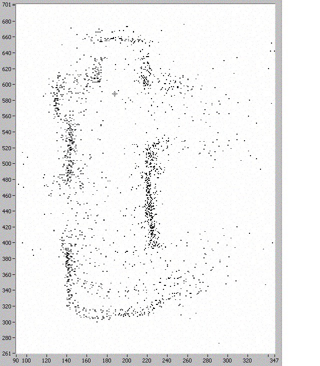
I noticed that the shorter-distance rangers seemed to max out at about a meter. Even if they noticed something 3 meters away, it would be reported as a meter. So I think the curved arcs down the middle of the hallway were false readings from them. Part of the algorithm would have probability curves assigning confidence of a measurement's reliability.
This is the same hallway with probability mapping and 2 dimensional motion tracking in the controller software.
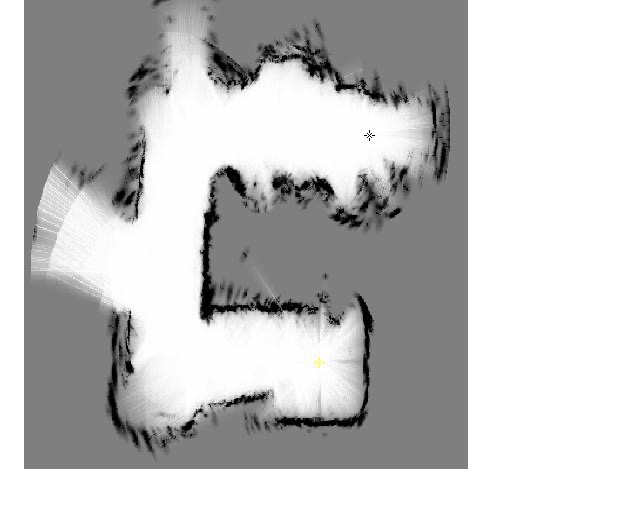
The occupancy map is now a greyscale indicating probability of being occupied. The range information modifies the map toward probability or non-probability of being occupied. The range sensor information is distance-limited to avoid erroneous readings. Each range-measurement beam is estimated as a sector with higher likely hood of correct detections being in the center of the sector. This effect can be seen at some the the extremities of the image where there was less dwell time. The probability methods and the range limiting eliminated most of the noise seen in the previous map.
There is an open door into a large room at the middle-left of the image. The lower part of the image is in a small bathroom with a door that is not completely open. The upper part of the image is in a walk-in closet with linens, shoes and clothes at robot-level. These give uneven response or no response (like the apparent passageway at the top - that doesn't exist).
I made this map by pushing the robot because the main controller software did not yet have a movement planning algorithm. The controller software constantly queries the motion MCU for position and the MCU counts encoder lines even when the motors are not driving, so it was able to know where the robot was all the time.
I developed a motion planner with three major components. Each component only referenced the map that had been created in memory.
- Foward motion was enabled if the space in front of the robot was known to be clear of obstacles.
- Looking to either side, the robot would follow a wall (within a limited capture distance) or stay mid-way between walls (as in a home hallway).
- If the way forward was blocked, the robot would look for the closest, largest area of grey (unmapped area) within "eyeshot", and turn in place to face it.
In general, the combination was quite successful. The robot could navigate hallways with corners. It only bumped into things that were not in its sight. Since there is noise in the mapping data, there is quite a bit of randomness introduced into the movement planning. This enabled the robot to overcome local difficulties such as an object that was partially blocking its path.
The part that gave me the most difficulty was the last component (turning the desired amount). Early on I had worried that the sloppy velocity control of the MCU motor controller would be a problem, and this did seem to be true.
Four mapping runs: Three are in a room approximately 10' x 15'. The last one is a hallway that was extended by barriers. The robot was placed in a random orientation each time, so the map orientation was different.
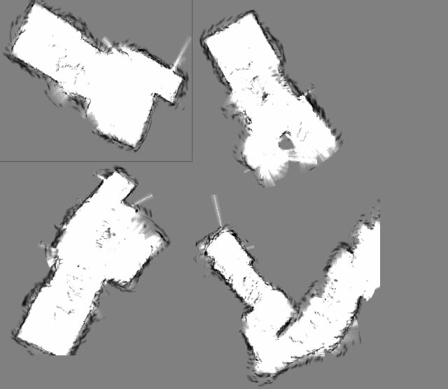
In the top-left mapping run, the floor was unobstructed. There seem to be a few defects in the map. There are some markings in the middle, but I do not know the mechanism for them at this time. (They may be cells that randomly did not receive mapping probably information.) There is a white spike sticking out that is a startup artifact from the rangers that I hadn't fixed.
The bottom-left run has a round bucket in the larger area. The upper-right run has a cooler in the middle (lengthwise) and a round object in the larger area where the bucket had been. (I stopped it before it completed mapping that end of the room.)
Conclusion
My advisor had recommended that I simplify the problem to be solved by the this robot by simplifying its environment. For example, put reflective tape on the floor of the area to be mapped so that very simple (and foolproof) downward-looking reflective sensors could be used. He was concerned that I not bite off more than I could chew. However, I knew that I could make a more complex machine.
Of course, the robot still does simplify its world by seeing it only in 2 dimensions and all walls as being solid. It moves fairly slowly (about 1 - 2 inches per second). I thought I would put the laptop on the computer. However, it was more convenient to use a long wire and connect to a stationary computer. In the end, it does a pretty good job for its task. It is pretty cool to see the robot move into narrow hallways without bumping walls, and navigate around corners.
I got a good grade for the class, but more importantly I really enjoyed doing the project.
Previous: Sub-systems
