
Next: Sub-systems
Autonomous Robot
An Independent Study Class
In July 2004, I was in a degree program at the UW Bothell. One quarter had no classes that I desired, so I chose an Independent Study class to fill 5 credits. My proposal was to build an autonomous robot. The goal for the robot was to map an enclosed office space. This would cover a lot disciplines and yet was an achievable goal.
Much of the text of this on-line report went into the final paper, but most of the pictures stayed only here.
Initial design decisions and finding the parts
I had followed the popular robot culture. I owned a copy of the excellent book Mobile Robots: Inspiration to Implementation by Jones and Flynn (amazon) and had been thinking about building a 'bot for a long time. Out of this I settled on a design partition that I hoped would leverage simplicity and still be expandable to handle unforeseen problems.
I would use a differential (wheelchair) drive on a low flat platform. Individual microcontrollers (MCUs) would provide interfacing to the real world. They would communicate with each other and with a main controller by serial interface. The main controller would be a laptop sitting on the platform.
I probably took too long deciding on locomotion. I had hoped to use motors I had in the junk box. However they were all unsatisfactory for one reason or another. So I decided to use the motive guts from RC hobby servos. Main wheels came from in-line skates and I went for one of those cool universal-direction wheels for the castor.

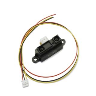
Since the robot was to perform mapping it would need range-finding sensors. Sharp has a line of optical triangulation sensors (with a good reputation) that I decided to use. Their output is not proportional to distance. The MCU would digitize the value and the laptop would perform the conversion math.
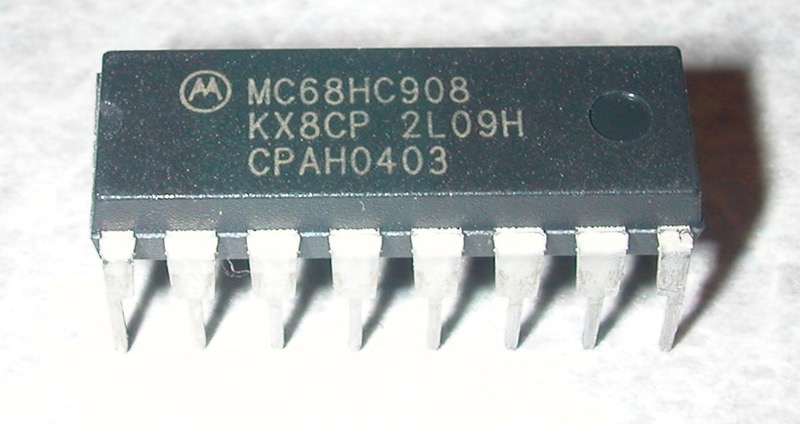
I wanted completely contained MCU devices. The PIC processor line and some members of Freescale's (nee Motorola's) 'HC08 line fulfilled this requirement. I had worked with Freescale 8-bit MCUs before and liked their flat-memory architecture, stack orientation and instruction set. The PICs seemed to have architecture quirks that I didn't feel comfortable with, so in the end I chose the an 'HC08.
This 68HC08KX8 unit has 8K flash, 198 bytes RAM, Pulse Width Modulation (PWM) control, timers, analog to digital converter (ADC), RS-232 serial, on-chip clock generation and many other features. Once programmed it only needs power to be useful. It is a 16 pin IC, available in a standard through-hole DIP package. The 'HC08 units have built-in breakpoint hardware and built-in ROM that supports a debug mode. Two pins are needed for chip power, and the debugger needs as few as three more pins. There are a few other details, but basically that leaves 11 pins for I/O.
Metrowerk's industrial-strength Codewarrior Integrated Development Environment (IDE) was available for free use with modest code size license limits. It supported C, C++ & assembly and had an integrated MCU simulator and debugger in the same interface.
Edit 15 years later: If I were to re-do this I would probably use an Arduino (compatible), but that was not available yet.
The IDE comes with tools that can create drivers for the on-chip peripherals. The abstraction could be useful for someone familiar with the their capabilities. However, I found it more productive to write drivers myself in assembly because it enhanced learning and then I knew what the code was doing. Initially because I was comfortable in assembly I thought I would do the whole project in it. However, later when I needed to do more than single-byte arithmetic, I found the C to be valuable.
Initially I thought to use a different member of the 'HC08 family for the project. However after I had invested some time into that one, I found that it did not have hardware support for serial communications. Software could do the job, but I didn't want to dedicate that much computing budget to serial. I was very glad to find the 68HC08KX8 that has serial in hardware.
Development started with some practice programs to learn control of the chip. Because there were no parallel interfaces to contend with (for example to external memory), I could even make these circuits on a solderless breadboard. It was very useful for this phase.
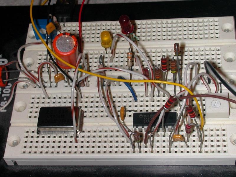
A related point is that I didn't want to buy a processor board with a turnkey robotic control environment because I wanted the practice of software development closer to scratch. The self-contained execution environment of these chips makes hand-built circuits possible. And I expected to find these chips useful for other types of projects into the future.
Physical platform
I found an aluminum shroud from a junked piece of equipment. The aluminum was easy to work, light and strong. So many of the robots I had seen on the internet looked fragile. I was able to build mine to be sturdy.

Next: Sub-systems