Construction
Although a solderless breadboard may be useful for inital prototypes, something more durable was needed for the robot. After hand-drawing the circuits, I used a combination of wirewrap and point-to-point construction.
|
|
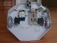
Motion controller: The chip in the middle of the motor controller circuit board is the MCU. Below-left is a logic inverter. And below-right is a dual H-bridge (TI SN754410NE) motor driver circuit. The board also has passive noise and interface parts.
The little green board is a voltage level shifter that converts between the 5-volt serial levels of the MCUs and the standard voltage levels of RS-232 serial.
|
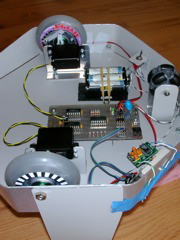
The battery pack puts out about 7.5 volts. Each board has a voltage regulator for the 5 volts required by the logic circuits. The H-bridge uses the higher voltage directly. The regulators enable noise isolation between circuits. Because the frame is conductive aluminum, I used the trick used in cars and made the body be the negative power conductor.
|
|
Hidden between the frame and the wheels are Hamamatsu photoreflector sensors that read the encoder stripes glued to the wheels.
|
Motion control
Motion control needs to be closed-loop for this robot because straight-line movement requires the drive wheels to have matched velocity. I followed the techniques used in Jones & Flynn which is velocity-oriented. It works, but control is a bit sloppy. It would not have been good enough for mapping except that I additionally count encoder lines so I can know how far it did move. It is likely that a position-oriented control algorithm would do better in this situation.
In more detail, since the chip has 2 PWM outputs, I was able to control both motors with one MCU. Each wheel has a one-bit optical encoder with a resolution of 40 lines / revolution. The motors produce 2 revs / sec at full speed. Since velocity is determined from line count / unit time, I would have difficulty getting good velocity resolution at low speeds and/or high update rates. To help things I used a technique that measures the period of each line count. Since it would be best to calculate the velocity at regular intervals, it counts line events and sums the total period for those events. Velocity is proportional to count / total period.
The method in Jones & Flynn uses techniques from classic Proportional-Integral-Derivative (PID) control. A velocity is commanded to the software and a velocity is measured. The power sent to the motors (by PWM control) is in direct proportion to the error between the set and measured values. The measured velocity difference (error) between the two is accumulated (integrated). A proportion of this second error is also added to the motor power values so that ongoing differences between the velocities of the two is continually forced to zero.
A significant improvement to the motion system would be to increase the encoder lines / rev. At present it is 40. If it were (for instance) 1000 counts / rev, then I could increase the update rate for tighter control and still have better resolution. However, it may be physically difficult to achieve a higher encoder resolution.
The position-based alternative method would need to use the physical resources of the MCU differently. So it would require an MCU for each motor.
|
Range sensing
The optical range sensors pulse their illumination LED with a fairly high current for increased range and signal noise immunity. This can produce significant electrical noise spikes. Attention to power (especially grounding) and modest capacitive filtering can control this.
|
|
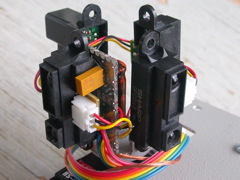
IR range finder head.
|
|
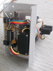
IR range finder controller and motion
|
For the range finders I am interested in range information in a full circle around the 'bot. I could sweep in a circle with either the 'bot itself, or I could use with a separate sweep mechanism. Since I am already concerned with accuracy of 'bot positioning, I don't want it to move unnecessarily. In addition the finders have only a 40 ms update rate, so I can't scan them around too fast. My solution was to use a set of rangefinders in an X configuration mounted on an RC servo. They will be swept back and forth. Paralleling the four will increase the speed of data acquisition.
|
|
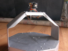
Range finder mounting bridge.
|
Raising them above the robot platform will avoid noise from floor reflections. In this case the 'HC08KX8 chip does all the interfacing: generation of the servo pulse train (for automatic sensor scanning) and digitization of the sensor data. Power and (serial) data are the only connections to the module.
|